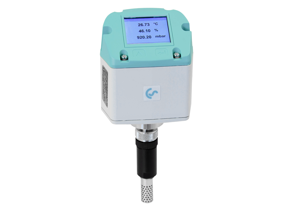
IAC 500 sensor for measuring ambient conditions
incl. wall bracket (abs. Pressure, Temperature, Rel. humidity)
The Efficiency and reliability of Compressed air generation depends largely on the quality of the intake and ambient air. When planning compressed air stations, careful consideration must therefore be given to the location and climatic conditions, which can vary throughout the year.
Extreme temperatures and humidity conditions as well as low air pressure are particularly challenging.
The IAC 500 measures temperature, humidity and air pressure continuously. Easy integration into an existing system is possible thanks to the communication interfaces via Modbus RTU or Modbus TCP.
Large temperature fluctuations (such as between day and night) and pressure fluctuations (high and low pressure or clogged ventilation filters) can lead to irregular delivery rates and require a corresponding reserve during planning. During humid days, the air can absorb many times more moisture than on cooler days, which leads to an increased water vapour content in the system.
In unfavourable cases, the warm, humid intake air can even lead to condensation in the Compressor if the compressor is poorly utilised, resulting in rust formation, premature ageing of the Oil and a shortened service life of the components. In addition, the compressed air outlet temperatures increase at higher intake temperatures, which in turn means more water vapour in the compressed air network and can impair the efficiency of the dryers.
If the installation location of the Refrigeration dryers is too warm, this also reduces the drying capacity. This can lead to unwanted condensate in the compressed air.


Example calculation winter:
Temperature: 0 °C
Max. Humidity at 0 °C: 4.85 g/m3
Relative humidity: 50%
Working time: 8h
Compressor delivery rate: 10 m3/min
Example calculation summer:
Temperature: 25 °C
Max. Humidity at 0 °C: 23 g/m3
Relative humidity: 70%
Working time: 8 h
Compressor delivery rate: 10 m3/min
At higher temperatures and corresponding humidity, many times more water enters the compressed air network, which puts a strain on the downstream components and can result in expensive maintenance or production downtime.
The location and the intake conditions also have a significant influence on the Compressor's delivery performance. Manufacturers often specify the performance under standard conditions in accordance with ISO 1217. This corresponds to the following intake conditions:
Temperature = 20°C, Pressure = 1 bar(a) Relative Humidity = 0 %.
To ensure that the Compressor provides sufficient performance under the most unfavourable intake conditions, the highest temperatures, lowest air pressures and maximum humidity at the site must be taken into account. The influence of humidity is not considered in the following calculation for the sake of simplicity.
The general gas equation states that the product of p*V/T is constant under all conditions.
Comparison of the intake volume required to generate 100 m3/min (ISO 1217) at different installation locations
Installation of a Compressor at sea level vs. installation at 1000 m altitude
| Suction conditions at sea level | Suction conditions at 1000 m altitude | Discharge conditions ISO 1217 | |
| Temperature: | 20 °C = 293 K | 20 °C = 293 K | 20 °C = 293 K |
| Air pressure: | 1013.25 mbar(a) | 891 mbar(a) | 1000 mbar(a) |
| Intake volume: | 98.69 m3/min | 112 m3/min | 100 m3/min |


Comparison of the intake conditions for an installation at sea level with an intake temperature of 20 °C vs. an increased intake temperature of 45 °C.
| Intake conditions at sea level | Intake conditions at 1000 m altitude | Outlet conditions ISO 1217 | |
| Temperature: | 20 °C = 293 K | 20 °C = 293 K | 20 °C = 293 K |
| Air pressure: | 1013.25 mbar(a) | 891 mbar(a) | 1000 mbar(a) |
| Intake volume: | 98.69 m3/min | 112 m3/min | 100 m3/min |
